


These days LCD modules become cheaper and cheaper and finally they are getting to the point when it is practical to use them for hobby projects without substantial budget increase. Not only projects significantly gain in functionality and usability but also in aesthetic matter. So we decided to test one of these LCDs and have a look what it can do and what it can’t. After some shopping around our choice has fallen to 3.2″ TFT LCD Module Display that was advertised on ebay. The list of claimed features was quite impressive: brand new display, 3.2 inches with resolution of 320×240 pixels, 262k colors, touch screen controller, SD card socket and 8/16 bit data bus – all this was for just US $13.98 with free shipping.
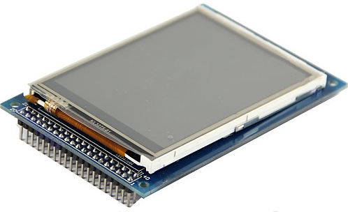
3.2″ TFT LCD Module Display + Touch Panel PCB Adapter SD Card Socket 240X320
The item was shipped next day after payment and was delivered a few days after – promising beginning. But there were a few little surprises upon close up visual inspection of the arrived item. First of all, it didn’t look like brand new. There were many scratches on the display’s protective film and evidences of manual re-soldering of one chip on the PCB’s bottom side. The seller didn’t want to damage his feedback history and quickly admitted that the item’s condition might be not immaculate. Then, to save his time and money, he basically suggested to refund half of the costs. Before we gave him a definitive answer we wanted to make sure if the display was functional at all. And immediately faced the second problem – it was absolutely unclear what type of display it was and where to find its 40-pin header pinouts. Normally, such displays have a pinout table on the bottom PCB’s layer, this one didn’t have anything. Also it would be very helpful to find schematic diagram to figure out what components have been used and how they interact with each other.
We searched the Internet for any similar display and found ITB02 module from Itead Studio which has been documented quite extensively and which came with circuit diagram, chip datasheets, detailed pictures and C libraries. Everything looked the same but the was… pinouts mismatch. ITB02 module had powerful software support of UTFT library designed by Henning Karslen but it order to use it we still needed to find pinout for our module.
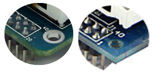
LCD’s pinout mismatch
Eventually a module with the same header pinout has been found, it was Connan TFT-3.2. Connan came with absolutely horrible schematic diagram, half-English / half-Chinese and messy library/demo code. As it turned out, in our possession was one of these modules with no silkscreen legend and SSD1289 LCD controller instead of HX8347. Further comparison with UTFT_Requirements.pdf from UTFT library revealed that pin designations were somewhat the same for both display types, the really difference was in the actual pin numbering – pins from 1 to 20 were numbered in the opposite order! As a result of the effort the following table below was created, defining relation between signal names and pin numbers for both display modules.
| Signal name | ITDB02 (orig.) | Connan TFT – 3.2 | Cmts |
|---|---|---|---|
| DB0 | 21 | 21 | |
| DB1 | 22 | 22 | |
| DB2 | 23 | 23 | |
| DB3 | 24 | 24 | |
| DB4 | 25 | 25 | |
| DB5 | 26 | 26 | |
| DB6 | 27 | 27 | |
| DB7 | 28 | 28 | |
| DB8 | 7 | 14 | |
| DB9 | 8 | 13 | |
| DB10 | 9 | 12 | |
| DB11 | 10 | 11 | |
| DB12 | 11 | 10 | |
| DB13 | 12 | 9 | |
| DB14 | 13 | 8 | |
| DB15 | 14 | 7 | |
| RS | 4 | 17 | |
| WR | 5 | 16 | |
| RD | 6 | 15 | Must be pulled high (3.3v) |
| CS | 15 | 6 | |
| REST | 17 | 4 | |
| LED-A | 19 | 2 | LED backlight, connect to +3.3v rail |
| GND | 1 | 20 | |
| VCC | 2 | 19 | +5v or +3.3v (see descr. below) |
UTFT library had a detailed description of how to connect LCD modules to a variety of Ardiinos and Chipkits. However, it had a few very important things missing.
First, it was not explicitly stated anywhere that these LCD modules ARE NOT 5v tolerant. Surely, it is possible to power them from 5v source but signal lines and LED backlight must not be exposed to levels greater than 3.3v. At the same time, many Arduinos work in 5v range so strictly speaking level converters should be used, for example, like ITDB02 Arduino Shield. All this, undoubtedly, makes the total project cost higher and dimensions bigger.
Secondly, it was not mentioned that LED backlight must be connected to +3.3v as well – without it the LCD’s usability becomes second to none as it is literary impossible to distinguish anything on its dark screen.
To make it even more confusing, our LCD contained 3.3v onboard regulator that obviously does not work if only +3.3v is applied to VCC pin – the voltage is just not high enough. There is a way to bypass the regulator if you power your LCD off 3.3v source – JP1 should be closed, making regulator’s input and output pins connected together.
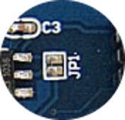
Bypassing voltage regulator – JP1 must be shorted
Now when it is clear with the LCD itself, it is time to physically connect it to a microcontroller and put everything together. We decided to test the LCD in tandem with Freeduino that had ATMega328p oboard with UTFT library. There was one trick to be made in order to fit everything into 32 kB – uncomment everything but #define DISABLE_SSD1289 in memorysaver.h so it would look like code snippet below. That way the final code was much more compact due to elimination of redundant code.
#define DISABLE_HX8347A     1 // ITDB32
#define DISABLE_ILI9327	    1 // ITDB32WC/TFT01_32W
//#define DISABLE_SSD1289   1 // ITDB32S/TFT_32/GEEE32/INFINIT32
#define DISABLE_ILI9325C    1 // ITDB24
#define DISABLE_ILI9325D    1 // ITDB24D/ITDB24DWOT/ITDB28/TFT01_24_8/TFT01_24_16
#define DISABLE_HX8340B_8   1 // ITDB22 8bit mode/GEEE22
#define DISABLE_HX8340B_S   1 // ITDB22 Serial mode
#define DISABLE_HX8352A	    1 // ITDB32WD/TFT01_32WD
#define DISABLE_ST7735      1 // ITDB18SP
#define DISABLE_PCF8833     1 // LPH9135
#define DISABLE_S1D19122    1 // ITDB25H
#define DISABLE_SSD1963_480 1 // ITDB43
#define DISABLE_SSD1963_800 1 // ITDB50
#define DISABLE_S6D1121     1 // ITDB24E
#define DISABLE_ILI9320     1 // GEEE24/GEEE28
We combined UTFT_Demo_320x240 with UTFT_Textrotation_Demo and UTFT_ViewFont, the resulting sketch is available here: Combined_UTFT_Demo_320x240
The Connan TFT-3.2″ LCD in action is shown below. There are the following drawbacks that we managed to find, both related to changing the displaying content. First, the overall transfer speed is not very impressive despite the fact that 16-bit bus was used. It takes a few moments to fill LCD’s video memory from its beginning to an end. This solution is obviously not for displaying moving sprites or updating the full screen a few times per second. Second problem is that there are some artifacts during the moments when graphical information is being updated – visually it looks like multiple flickering white dots and lines, there is also a possibility that we have a faulty LCD in our possession.

Connan TFT-3.2″ LCD in action
As a conclusion it would be worthwhile to highlight pros and cons of this LCD. Let’s start from the positive side:
1. Cheap and affordable,
2. Makes hobby projects to look professional and modern,
3. Great for rapid prototyping,
4. Excellent software support.
However, there are the following disadvantages:
1. A limited edition of ITDB02-3.2S with poorer quality and confusing pinouts,
2. Absence of documentation,
3. Intolerant to 5v signal levels,
4. No 1:1 compatibility with Arduino pins,
5. Too many signal wires with no significant advantage in performance if compare with LCD’s with serial interfaces,
6. Not very compact when used with Arduino and ITDB02 Arduino Shield,
7. Not cheap when used with ITDB02 Arduino Shield.
As a bottom line, a few dollars difference between Connan TFT-3.2 and ITDB02-3.2S and due to the abovementioned problems is not worth of buying Connan. And if the dimensions do make a difference then probably it would be better to use a TFT LCD panel like this one: 3.2 Inch TFT LCD Panel with Resolution 320 x 240.
And finally, as you probably noticed, we haven’t described all signals that are wired up to the LCD’s 40-pin header. There are datalines for interfacing with SD card and touch screen controller – they will be topics for our future articles.


Leave a Reply
You must be logged in to post a comment.