


Luminardo motherboard and MVFD 16S8D Panel were specifically designed to fit together. That is why both PCBAs have the same board outline and matching mount holes. Two PCBAs interconnected by a 2 row 14 pin header, named as P8 on motherboard side and as JP2 on VFD panel side. In order to do the assembling we will need 8 x M3x10 screws, 8 x M3 washers and 4 x M3x18 tapped nylon spacers. The process is rather trivial and takes just a few minutes to complete. Assembly parts are shown on the picture below:
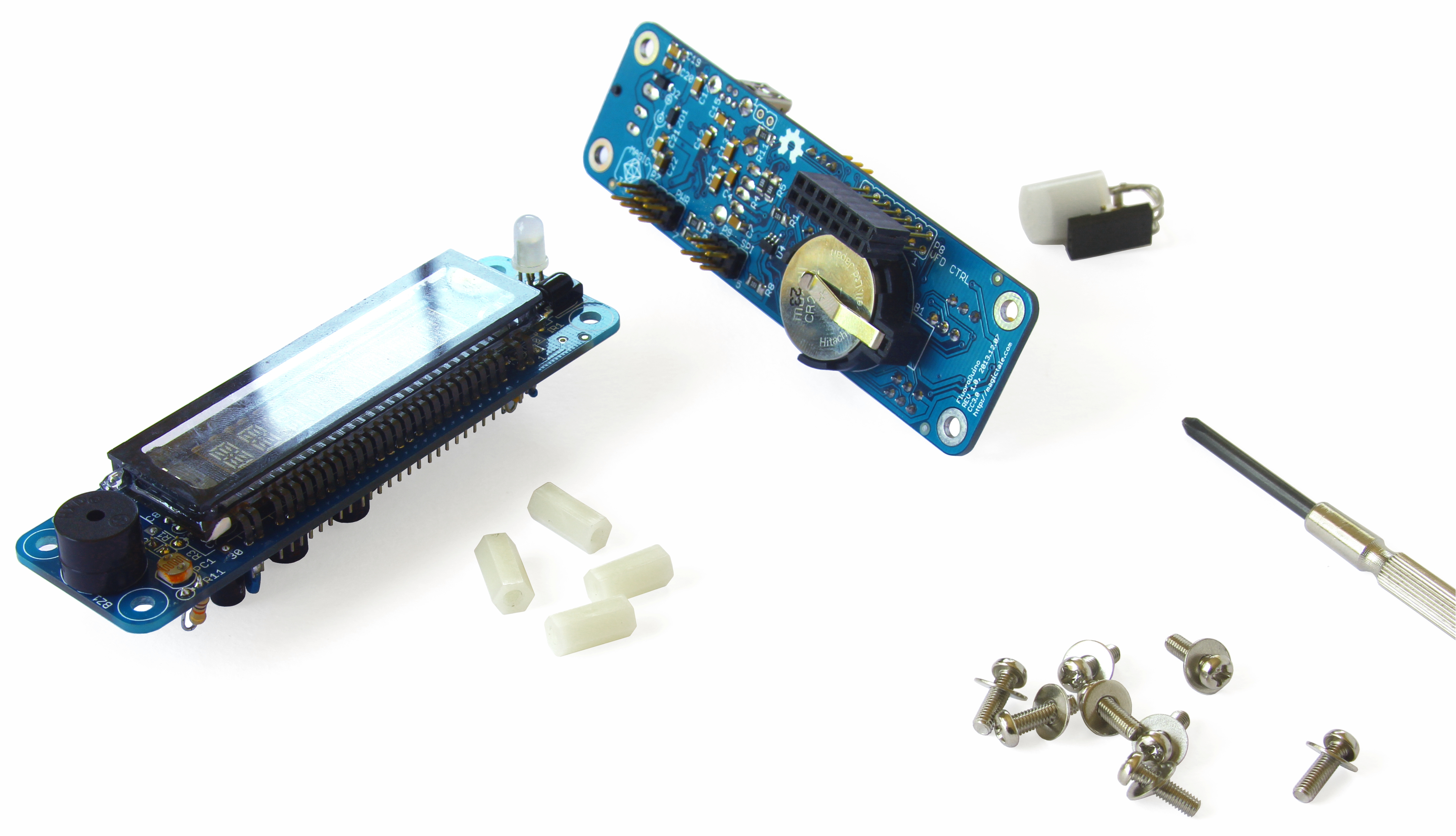
Luminardo Rev1.0 Assembly Parts
Assembling process is shown on video below:
Now we would need to use Luminardo source code again (previously we mentioned it here). Install VFD panel library if you haven’t done it so – copy Software\Arduino\Libraries\MVFDPanel_16S8D folder and its content to [ArduinoIDE_Install_Directory]\libraries. Restart Arduino IDE. Open
Software\Arduino\Sketches\Luminardo_MFVD_16S8D_Test\Luminardo_MFVD_16S8D_Test.ino sketch in IDE, make sure that ‘Luminardo 1284P 10MHz’ is still selected and try to compile the sketch. If all previous steps were done correctly, the sketch should compile successfully. Connect Luminardo with previously programmed bootloader to your PC by mini-USB cable. Wait until new virtual COM port appears in Device Manager, select appropriate serial port in Arduino IDE and try to upload the compiled sketch. Be aware of a little trick that helps to program Luminardo: as there is no RESET button in hardware rev1.0 sometimes it becomes difficult for Arduino IDE and the board to initiate handshaking before actual programming takes place. The reason for this is simple: upon boot up control is given to a Luminardo’s bootloader and it waits for incoming request just for a few seconds and if nothing received then bootloader gives control to Luminardo’s main application. On the other hand, Arduino IDE takes more than a few seconds to initiate upload after ‘compile and upload’ button is pressed so by the time when IDE is ready to upload Luminardo’s bootloader has already given up. The best solution for now is to power Luminardo when the Arduino IDE is about to finish compilation and initiate upload, the right moment is chosen experimentally and depends on sketch complexity and PC performance. When sketch upload is in progress two white LED’s on Luminardo motherboard repeatedly flashes to indicate data exchange as shown on video below:
When sketch upload is complete your Luminardo should become alive:
At this stage your Arduino IDE is configured correctly and most of Luminardo hardware is functional. Stay tuned, more tutorials are coming very soon.


Leave a Reply
You must be logged in to post a comment.