


The need in inexpensive, simple and compact power supply unit (PSU) for VFD projects has always been topical for us. MVFD 16S8D Panel was designed to address the challenge, however, as it always the case for first revision, there are some things which require improvements or rethinking. And MVFD Panel was not an exception in this sense. Let’s quickly highlight requirements for PSU:
– Single (5V) input voltage with filament and segment/grid voltages being generated internally;
– No transformers or custom winded ferrites;
– Pulse filament drive to avoid brightness gradient;
– Feedback for segment/grid high voltage to break dependency between brightness and number of illuminated segments;
– Shutdown mode;
– Overcurrent protection is highly desirable;
– Filament/segment voltages to be adjustable in reasonable range to make the solution as generic as possible in order to support more than just one type of VFD;
– Reasonable number of components, compact dimensions;
– High availability of components with no ‘end of life’ or ‘not recommended for new design’ things;
– All components must be handsolderable;
– The total cost of components should not be greater than $5-6;
On the other hand, the previous design had the following issues:
– LM9022 filament driver became obsolete;
– Segment/grid voltage was generated by a charge pump using pulse filament drive and making segment and filament voltages interdependent on each other leaving without possibility of fine tuning;
– Absence of feedback for segment voltage caused less segments to shine brighter and more segments to be dimmed;
– Five stages of charge pump require substantial area on PCB;
So in our next PSU revision we will aim to address most (if not all) issues of the prior design. After countless hours of search we finally found what we think would be a good candidate for high voltage generator. It is MC34063, buck/boost/inverting regulator which comes at a price of 56 cents from Digikey! However, it also has disadvantages, the biggest one is its maximum switching frequency which is just 100kHz. It automatically imposes much bigger inductance if compare with switching voltage regulators operating in 1-2Mhz. Values of 80…200uH are very typical for circuits with MC34063. In addition to that, due to low frequencies inductors must be capable of passing through currents 10 and even 15 times higher than the actual load requires. To some degree the price migrates from switching converter to passive components and it is important to be aware that in some circumstances it is just not worth using MC34063.
Another challenge is to calculator values of passive components, the quick approach would be to use already existing online calculators and there are few of them available, the problem is that they produce quite different results. We ended up using MC34063 Boost Converter Calculator as it looked more professional due to a mere fact that is distinguishes numerous flavors of MC34063 from different manufacturers. Filling in required input parameters we got the following results below.
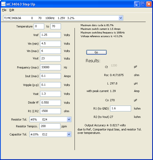
MC34063 Calculations
There are few things worth mentioning though. First of all, the calculator does not give anything if negative Vout is specified. Looks like it is unable to calculate for inverting mode (well, not a big deal, it should not fundamentally change anything if we provide positive value for Vout). Secondly, the calculator doesn’t give any result if we specify Vout = 24V. Well, we specified 23V and going to adjust value either of R1 or R2 to get 24V. If the prototype works then we keep 24V otherwise will stick to 23V as it is still within the optimum range of VFD. And finally, the calculated inductance is so high that it becomes unpractical, it also seems too high when looking at the application examples in the datasheet. There is a good article about a PSU based on MC34063, the author also got extremely high (389uH) inductance as a result of calculation and decided to use 100uH. We will also reduce calculated value down to 180uH and see what happens during our experiments. The first revision of our circuit is given on the picture below.

MC34063 Inverting -24V
After getting all the required components we finally were ready to begin experiments in real life. The first prototype didn’t give any magic smoke but even without load applied there was current consumption of 70mA @ 5VDC input voltage! MC34063 was unpleasantly warm. High current in idle mode must be caused by pulses going back and forth through big inductor and frequency of pulses is in essence switching frequency. Then by ramping up switching frequency pulses of current through inductor should be less and therefore loses should be less… To check our assumption we then measured power consumption when using 1200pF and 600pF timing capacitor. In first case current consumption was 70mA, the second experiment gave 60mA. So we managed to bring down consumption by 10mA – not ideal but we were definitely going in the right direction. Using oscilloscope we confirmed that switching frequency increased from 40kHz to about 73kHz as it is shown on the picture below. Potentially we still had some space for improvement as we could increase the frequency up to 100kHz.
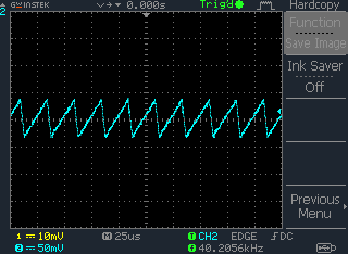
MC34063 1200pF @ 40kHz
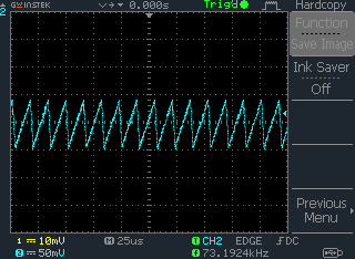
MC34063 600pF @ 73kHz
The picture below shows that the PSU indeed generates -24VDC out of +5VDC, however, it still consumes too much when idling.
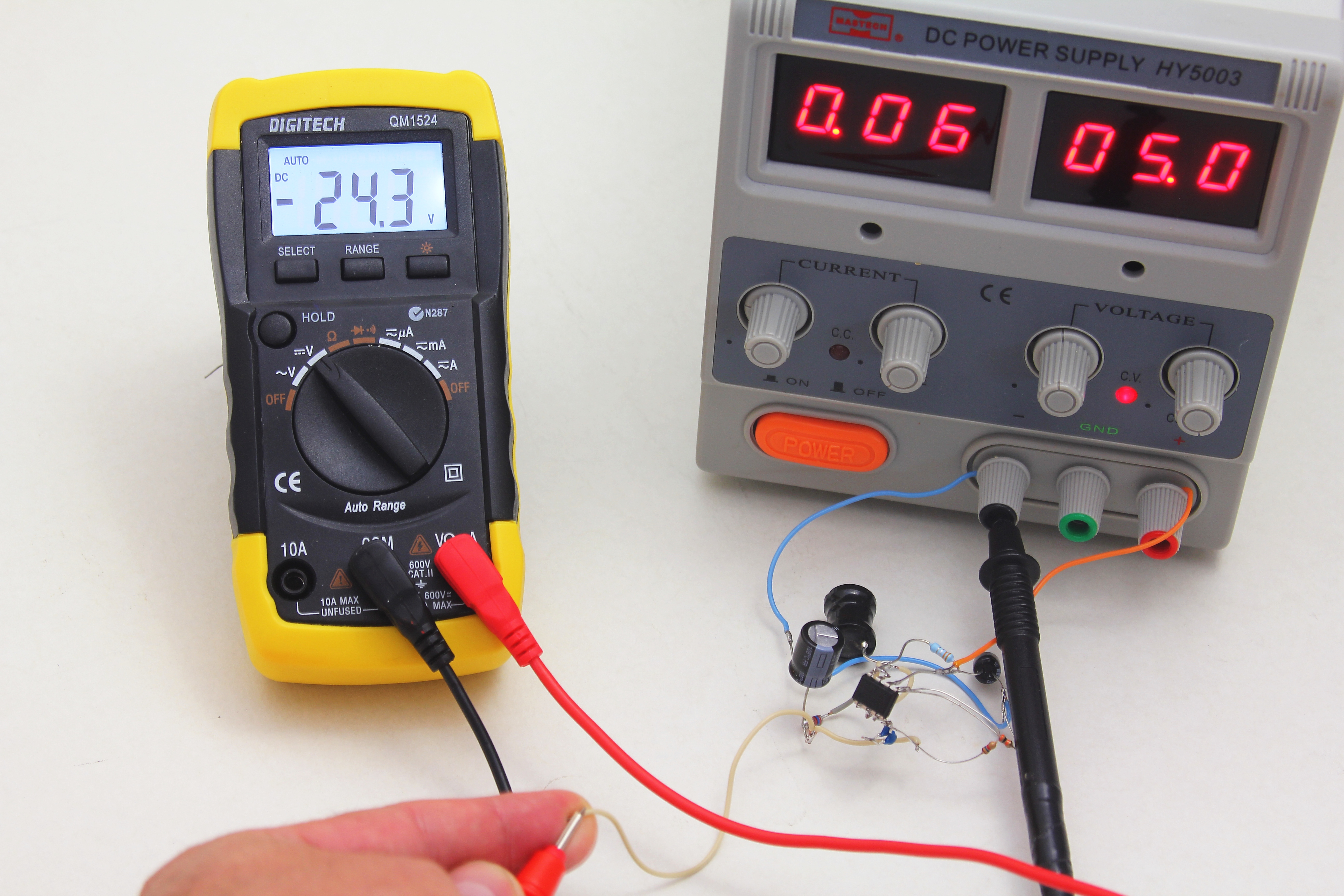
MC34063 5V to -23V PSU Idling
We are going to continue our experiments with the prototype to make it more efficient. It would also be quite interesting to know how good it is when it works with real load – all this will be done soon, stay tuned.


Leave a Reply
You must be logged in to post a comment.